Kaiyue Rubber (Jingxian): Delivering High-Quality Rubber & Silicone Products for Industrial & Daily Applications Worldwide.
English


Views: 0 Author: Site Editor Publish Time: 2026-10-14 Origin: Site


Did you know a simple miscalculation in hose sizing accounts for a massive percentage of catastrophic fluid power failures? I have seen this happen on countless job sites. Incorrect dimensions do not just lead to annoying leaks. They trigger costly downtime, environmental spills, and severe safety hazards. Finding the exact dimension is critical whether you are replacing a ruptured line on a skid steer or engineering a complex manifold from scratch.
This comprehensive guide breaks down the core metrics of fluid power conduits. We will decode the universal dash size system and explore global manufacturing standards. Finally, I will walk you through a foolproof measurement process to ensure your machinery runs safely and efficiently.
The Dash Size System is Universal: Industry professionals globally utilize Dash Sizes such as -4, -8, or -16 to indicate the inner diameter of a fluid line. This measurement is standardized in sixteenths of an inch, providing a uniform language for engineers and technicians.
Inner vs. Outer Diameter: The inner diameter strictly dictates fluid flow velocity and system efficiency. Conversely, the outer diameter is crucial for selecting the correct fittings, ensuring proper crimping, and routing the assembly safely through tight mechanical spaces without abrasion.
Standards Matter: Sizing, safety factors, and performance metrics are heavily regulated by international global standards. Organizations like SAE and EN dictate strict specifications for various constructions, ensuring operational reliability under extreme pressures.
The STAMPED Framework: Selecting the perfect replacement requires evaluating seven critical parameters. These include Size, Temperature, Application, Material, Pressure, Ends, and Delivery. Skipping any of these steps can compromise system integrity.
Designing a hydraulic circuit requires precision. Empirical data proves that exact dimensional matching is non-negotiable. The geometry of any fluid line relies on three primary metrics, and each serves a distinct mechanical and fluid dynamics purpose.
The inner diameter is universally recognized as the most critical dimension in hydraulic system design. It determines the cross-sectional area available for fluid travel. This directly impacts the flow rate measured in Gallons Per Minute or Liters Per Minute and the overall fluid velocity.
Based on fluid dynamics principles, selecting an inner diameter that is too small for the required flow rate increases fluid velocity excessively. This creates turbulent flow, leading to severe pressure drops, excessive heat generation, and potential damage to pumps and valves. On the flip side, if the dimension is too large, the fluid velocity drops. This results in sluggish system performance and delayed actuator response times. Furthermore, oversized lines are heavier, more expensive, and incredibly difficult to route through cramped engine bays.
The outer diameter measures the entire cross-section of the assembly. This includes the inner tube, the reinforcement layers, and the outer cover. This metric is primarily used when selecting compatible ferrules, mounting clamps, and protective sleeves.
Specifically, the outer profile varies significantly depending on the pressure rating and internal construction. For example, a Single Wire Braided Hydraulic Hose built to SAE 100R1 standards features a noticeably slimmer profile compared to a four-wire spiral variant of the exact same inner dimension. This single layer of high-tensile steel wire allows for tighter routing while still handling working pressures up to 3270 PSI in smaller sizes. Accurate outer measurement prevents the line from rubbing against adjacent moving machinery. This rubbing remains a leading cause of premature abrasion failure.
Length measurements in fluid power assemblies require careful calculation. The overall length refers to the total distance from the end of one fitting to the end of the other. Meanwhile, the cut length refers strictly to the raw rubber section before fittings are attached.
Engineers must account for the physical behavior of rubber under pressure. When pressurized, a hydraulic line can expand or contract. It typically changes in length by up to positive 2 percent or negative 4 percent. Therefore, installations must include calculated slack. Pulling a line completely taut guarantees that the fittings will eventually be ripped off during sudden pressure spikes.
To eliminate confusion between metric and imperial measurement systems across different countries, the fluid power industry adopted the Dash Size system. This standardized naming convention acts as the absolute backbone of hydraulic sizing.
A dash size is a shorthand method used to express the inner diameter of a hose. The dash number represents the numerator of a fraction where the denominator is always 16. Therefore, the dash size translates directly to sixteenths of an inch.
A -4 hose equals 4/16 of an inch, which simplifies to a 1/4 inch inner diameter.
A -8 hose equals 8/16 of an inch, which simplifies to a 1/2 inch inner diameter.
A -16 hose equals 16/16 of an inch, which simplifies to a 1 inch inner diameter.
To ensure accuracy during replacement or design, technicians rely on standardized conversion charts. Below is a comprehensive reference table detailing standard dash sizes alongside their fractional, decimal, and metric equivalents.
Dash Size | Inch Fraction | Inch Decimal | Millimeters |
|---|---|---|---|
-4 | 1/4 inch | 0.250 inch | 6.4 mm |
-6 | 3/8 inch | 0.375 inch | 9.5 mm |
-8 | 1/2 inch | 0.500 inch | 12.7 mm |
-10 | 5/8 inch | 0.625 inch | 15.9 mm |
-12 | 3/4 inch | 0.750 inch | 19.0 mm |
-16 | 1 inch | 1.000 inch | 25.4 mm |
-20 | 1-1/4 inch | 1.250 inch | 31.8 mm |
-24 | 1-1/2 inch | 1.500 inch | 38.1 mm |
-32 | 2 inch | 2.000 inch | 50.8 mm |
While the dash size system almost universally applies to the inner diameter of standard fluid power lines, prudent technicians must be aware of exceptions. Certain specialized products, such as SAE J51 refrigerant lines or specific air brake transportation tubes, use dash sizes to refer to the outer diameter of the matching rigid tubing. However, for traditional machinery applications, the dash size always denotes the internal measurement.
Heavy machinery operates under immense stress. Strict adherence to manufacturing standards acts as a critical safety net. This ensures a component built in Europe safely interfaces with a pump designed in North America.
Lately, the industry is experiencing a massive shift toward mobile equipment miniaturization. Equipment manufacturers demand higher working pressures packed into tighter, more compact spaces. How do we solve this? Engineers are innovating with advanced synthetic rubber compounds to achieve tighter minimum bend radii without sacrificing internal flow capacity. Furthermore, as predictive maintenance powered by smart sensors becomes standard across modern fleets, precise dimensional tolerances are more critical than ever. Sensor-equipped fittings must seal flawlessly under dynamic loads, meaning even a fraction of a millimeter off spec can trigger false alarms or system shutdowns.
The SAE J517 standard is the most widely recognized benchmark in the fluid power industry. It categorizes products into the 100R series based on their construction materials, reinforcement types, and maximum working pressures.
SAE 100R1 and EN 853 1SN: Engineered for medium-pressure applications, offering an optimal balance of flexibility and strength. The single layer of high-tensile steel wire dictates both its pressure threshold and its relatively compact profile.
SAE 100R3: Known commonly as a Low Pressure Hydraulic Hose, this variant utilizes dual textile braid reinforcement rather than steel wire. It typically handles pressures up to 1500 PSI in smaller diameters. It is highly flexible and perfectly deployed in return lines where heavy wire reinforcement is simply overkill.
The sizing principles established by SAE and EN extend well beyond pure hydraulics. Broad Industrial Rubber Hose applications often adopt similar measurement frameworks. These range from agricultural chemical transfer to heavy construction water discharge. While industrial variants typically prioritize chemical compatibility and abrasion resistance over extreme high-pressure capabilities, understanding this dimensional crossover is absolutely essential for multi-industry fleet maintenance.
Guesswork has no place in machinery maintenance. A measurement error of just a few millimeters can lead to fitting blow-offs, causing severe environmental spills and equipment damage. Following a standardized operating procedure ensures exact replacements every single time.
To achieve empirical accuracy, technicians should utilize a digital caliper calibrated in both millimeters and decimal inches. You will also need a flexible industrial measuring tape and a thread pitch gauge for identifying fitting terminations.
Never measure a crushed or degraded piece of rubber. Your readings will be completely useless. First, ensure the system is completely depressurized. Cut a small section of the raw material using a specialized fine-tooth saw to ensure a clean, perfectly perpendicular edge. Insert the internal jaws of the digital caliper into the opening to measure the inner dimension. Ensure the jaws lightly touch the inner tube without compressing the rubber. Next, use the external jaws to measure the outer profile across the outermost cover. Record both measurements.
Once you have the internal dimension in decimal inches or millimeters, consult the conversion chart to find the corresponding Dash Size. For example, if your caliper reads 12.7 mm or 0.500 inches, you divide 0.500 by 0.0625. The result is 8, confirming you require a dash 8 replacement.
When fabricating a replacement assembly, lay the old line completely flat. Measure the overall length from end to end. Note the sealing surfaces carefully. For Joint Industry Council fittings, measure to the end of the flare. For O-Ring Face Seal fittings, measure directly to the flat sealing face.
Selecting the correct internal dimension is a matter of physics. Comparing a standard 1/4 inch hose with larger dimensions, such as a 1/2 inch or 1 inch variant, highlights how key performance metrics scale with size.
There is a fundamental inverse relationship between the internal dimension and maximum working pressure. According to standard engineering principles governing hoop stress, a smaller internal surface area means less total force is exerted against the walls by the pressurized fluid. Consequently, a 1/4 inch line can typically withstand significantly higher working pressures with fewer reinforcement layers compared to a 1 inch line. To achieve high-pressure ratings in larger sizes, manufacturers must utilize heavy, multi-spiral wire constructions. This drastically increases the outer profile and reduces overall flexibility.
Larger sizes are mandatory for high-volume applications. A 1/4 inch line is typically limited to low flow rates between 1 to 3 Gallons Per Minute to keep fluid velocity within safe parameters. Forcing 10 Gallons Per Minute through a 1/4 inch circuit will cause severe turbulence, heat, and potential cavitation that can destroy expensive pumps. Conversely, a 1/2 inch or 1 inch line provides the necessary cross-sectional volume to facilitate high flow rates smoothly.
Smaller lines offer superior routing flexibility. A 1/4 inch variant possesses a very tight minimum bend radius, allowing it to navigate compact spaces in mobile machinery easily. Larger assemblies require significantly more spatial clearance. Forcing a massive 1 inch assembly into a tight radius will cause the reinforcement wires to fatigue and the inner tube to kink, leading to premature failure.
To navigate the complexities of fluid power specifications, industry professionals universally rely on the STAMPED acronym. This robust decision-making checklist ensures that every critical variable is evaluated before a component is procured or installed.
S - Size: This encompasses the exact inner diameter required for proper fluid velocity, the outer diameter for fitting compatibility, and the overall length of the assembly.
T - Temperature: Technicians must evaluate both the ambient temperature of the operating environment and the internal temperature of the hydraulic fluid. Extreme cold makes rubber brittle, while excessive heat accelerates degradation.
A - Application: The specific use case dictates exterior requirements. For instance, an application in a harsh mining environment may require an ultra-high abrasion-resistant cover.
M - Material: The inner tube rubber compound must be chemically compatible with the system fluid. Petroleum-based oils require different rubber polymers compared to synthetic water-glycol fluids.
P - Pressure: The maximum working pressure must equal or exceed the maximum system pressure, including sudden transient spikes. Industry standard dictates a four-to-one safety factor.
E - Ends: Identifying the correct thread type like NPT, JIC, BSPP, or metric and connection style is mandatory for a leak-free seal. Installing a mismatched fitting inevitably results in violent blow-offs.
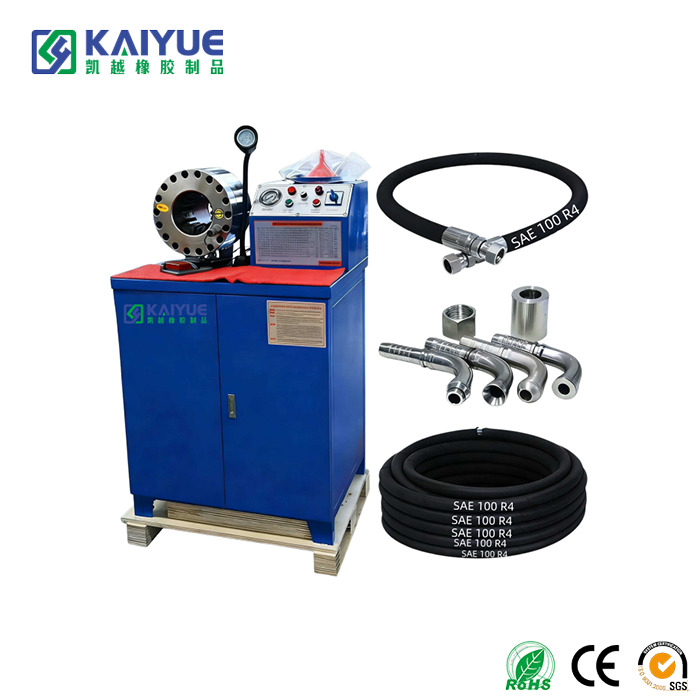
D - Delivery: This refers to the required fluid volume, velocity, and the specific nature of fluid movement. Does the application involve drawing fluid from a reservoir to a pump? Standard lines will collapse flat under negative pressure. These specific scenarios demand a dedicated Hydraulic Suction Hose. Built to SAE 100R4 standards, this type incorporates a rigid helical steel wire specifically designed to prevent structural collapse during severe vacuum conditions.
In the fluid power industry, dimensions are standardized using a Dash Size system. A dash number represents the inner diameter in sixteenths of an inch. Therefore, a dash 8 indicates an inner diameter of 8/16 of an inch. When simplified, this equates to a 1/2 inch inner diameter. This system is universally applied across SAE and EN standards, allowing technicians to quickly identify flow capacities regardless of the manufacturer.
Determining the correct size requires calculating the required fluid flow rate and the target fluid velocity for your specific circuit type. Engineers typically use a hydraulic nomogram. This is a specialized chart that aligns flow rate and velocity to pinpoint the exact required inner diameter. Guessing the size based on external appearance leads to system inefficiency and potential equipment damage.
Generally, replacing a line with a larger internal dimension is not recommended. While a larger dimension will reduce fluid velocity and minimize pressure drops, it can also lead to unintended consequences. A larger volume of fluid can cause sluggish actuator response times and alter the system operational dynamics. Furthermore, a larger internal dimension inherently brings a larger outer profile, which may not fit within your existing routing spaces or mounting brackets. Always adhere strictly to original equipment manufacturer specifications.
No, the outer profile varies significantly based on the pressure rating and internal construction. A 1/2 inch line designed for low-pressure return applications may only have a single textile braid, resulting in a relatively thin profile. In contrast, a 1/2 inch line engineered for extreme high-pressure applications will feature multiple layers of high-tensile steel wire spirals, resulting in a much thicker profile. You must verify the outer dimension to ensure compatibility with your specific fittings and crimping specifications.
Using the wrong outer dimension primarily causes fitting and crimping failures. If the profile is too large for the selected ferrule, the crimp will be incomplete, leading to a catastrophic blow-off under pressure. If it is too small, the fitting will not grip the reinforcement layers tightly enough, causing severe fluid leaks. Additionally, an oversized profile can cause severe abrasion damage if it rubs against tight machine chassis components.
Visual inspection is key, but operational hours dictate replacement schedules. High-pressure lines with smaller internal diameters often experience higher fluid velocities and heat generation, leading to faster internal tube degradation. As a general industry rule, preventive maintenance programs suggest replacing critical fluid lines every one to two years or every 2000 operating hours, regardless of external appearance. Always monitor for cover abrasions or weeping near the crimp ends.
Accurate sizing ensures system safety, operational efficiency, and extended component longevity. Bypassing standard measurement protocols invites catastrophic failures and expensive machinery downtime. Always measure dimensions carefully with digital calipers. Never guess your required specifications based on a quick visual glance.
By understanding dash sizes, respecting global standards, and applying the STAMPED method, you can confidently engineer robust fluid power systems. Ready to upgrade your equipment with perfectly sized, high-performance components? Explore the comprehensive range of premium fluid power solutions at Kaiyue Rubber to find the exact match for your specific operational demands.


