Kaiyue Rubber (Jingxian): Delivering High-Quality Rubber & Silicone Products for Industrial & Daily Applications Worldwide.
English


Views: 0 Author: Site Editor Publish Time: 2026-10-07 Origin: Site


A heavy-duty excavator operating at peak capacity suddenly halts with a deafening pop. Hydraulic fluid sprays across the machinery, triggering an immediate and messy shutdown. Did a wrong conveyance line ever cause a catastrophic system failure in your facility? This scenario happens far too often in industrial environments. Pressure ratings stand as the absolute most critical specification for fluid power systems. Purchasing the incorrect component frequently leads to exorbitant downtime, environmental cleanup costs, and severe safety hazards. In this guide, we break down pressure ratings from a field engineer's perspective, explore how different reinforcement structures dictate performance, and provide a clear framework to help you choose correctly every time.
Understand the Terminology: Grasping the exact difference between Working Pressure, Burst Pressure, and Test Pressure is essential for safe daily operation. You must never operate a fluid conveyance system at its burst pressure limit.
Reinforcement Matters: Fabric braiding is ideal for low-stress return lines, whereas multi-layered steel wire reinforcement is mandatory for high-impulse, heavy-duty environments.
Temperature Affects Pressure: As operating temperatures rise, the maximum pressure capacity of a rubber elastomer decreases. This physical reality requires strict pressure derating calculations.
The System is Only as Strong as its Weakest Link: The overall pressure rating of your assembly is strictly determined by the lowest-rated component, whether that is the line itself or the attached metal fittings.
Use the STAMPED Method: Always evaluate Size, Temperature, Application, Material, Pressure, Ends, and Delivery when making a technical purchasing decision.
At their core, pressure ratings are standardized engineering metrics. They define the absolute maximum internal force a fluid conveyance system can safely withstand. For procurement teams and maintenance managers, understanding these metrics goes far beyond mere functionality. It acts as the foundational requirement for workplace safety and equipment longevity. When hydraulic fluid or compressed air is pumped through a line, it exerts immense outward force against the inner tube and reinforcement layers. The pressure rating indicates exactly how much kinetic force those materials can contain before they deform, leak, or violently fail.
To make an informed and safe purchasing decision, buyers must distinguish between three distinct pressure classifications. Confusing these terms remains a primary cause of system failure on the factory floor.
Pressure Type | Technical Definition | Industry Standard Ratio |
|---|---|---|
Working Pressure | The maximum continuous internal pressure the component is designed to handle safely under normal, steady-state operating conditions. | 1x Baseline |
Test Pressure | The pressure applied during the manufacturing and quality assurance process to verify structural integrity without causing permanent damage. | 2x Working Pressure |
Burst Pressure | The absolute maximum pressure limit at which the reinforcement structure will catastrophically rupture and fail. | 4x Working Pressure Typically |
Selecting the correct rating requires a delicate balancing act between operational safety and economics. Under-specifying an Industrial Rubber Hose means you choose one with a working pressure lower than your machine's output. This mistake will inevitably trigger blowouts. A blowout in a high-pressure system releases trapped kinetic energy and hazardous fluids at blinding speeds. This poses lethal injection risks to nearby operators and destroys surrounding machinery.
In contrast, over-specifying results in unnecessary financial expenditure. Components designed for extreme pressures require thicker inner tubes and multiple layers of heavy steel reinforcement. This makes them heavier, incredibly stiff, and significantly more expensive. Furthermore, forcing a highly rigid, over-specified line into an application that requires tight routing and flexibility can cause severe mechanical stress on the machine's connection points. Accurate specification ensures the assembly safely handles operational surges without adding cumbersome bulk or inflated costs to the overall system design.
Moving beyond basic definitions, the physical architecture of the product directly dictates its pressure capacity. A standard assembly consists of three primary components. These include the inner tube containing the fluid, the reinforcement layer providing structural strength, and the outer cover protecting against environmental damage. Specifically, the material and geometric design of the reinforcement layer serve as the primary factors determining the maximum working pressure.
A Low Pressure Textile Braided Hydraulic Hose utilizes woven natural or synthetic fibers for its reinforcement layer. Common materials include high-strength polyester, cotton, or nylon. Because textile materials are inherently lighter and more pliable than metal, these products offer exceptional flexibility and a remarkably tight bend radius.
However, textile reinforcement cannot contain high-intensity internal forces. For instance, a standard SAE 100 R3 specification is typically rated for working pressures ranging from 225 to 1,500 PSI, depending heavily on its inner diameter. In industrial and mobile machinery, textile-braided variants are primarily deployed in low-stress applications. Common use cases include fluid return lines, lubricating oil circuits, and general-purpose water or air transfer where pressure spikes are virtually nonexistent.
When system pressures eclipse the structural limits of fabric fibers, engineers must transition to metal reinforcement. A Single Wire Braided Hydraulic Hose represents the industry's standard middle ground in fluid conveyance. This construction features a single layer of high-tensile steel wire woven in an overlapping crisscross pattern over the inner rubber tube.
The braided steel wire restricts the inner tube from expanding under pressure, significantly increasing the overall capacity. Depending on the governing standard like SAE 100 R1 AT or EN 853 1SN, this build delivers serious performance. Taking a quarter-inch inner diameter as an example, this single wire braided construction can safely handle continuous working pressures up to 3,270 PSI or 22.5 MPa. This build is highly favored by procurement officers because it provides a robust defense against medium-pressure hydraulic forces while still maintaining enough flexibility for standard, compact machine routing.
For punishing, heavy-duty environments such as mining operations, industrial stamping presses, and large-scale excavators, a High Pressure Hydraulic Rubber Hose becomes an absolute necessity. These rigorous systems frequently operate at pressures well exceeding 4,000 to 6,000 PSI. To contain such immense, volatile force, manufacturers utilize multiple layers of steel wire reinforcement.
In these extreme-pressure variants, the steel wire is often spiraled rather than braided. Spiral reinforcement consists of parallel wires wrapped tightly around the inner tube in alternating directions, typically spanning four to six distinct layers. This spiral architecture prevents the wires from rubbing against each other during high-frequency pressure impulses, drastically reducing internal friction and heat generation. Ultimately, this design minimizes volumetric expansion and maximizes burst resistance, making it the only viable choice for extreme hydraulic stress, albeit at the cost of overall flexibility.
As fluid power systems become increasingly sophisticated, the landscape of pressure rating compliance is shifting rapidly. Recent industry analyses reveal a growing demand for higher power density. Modern hydraulic machinery is expected to operate at significantly higher pressures within much tighter spatial footprints. Consequently, buyers are migrating toward compact, high-impulse spiral builds that deliver massive pressure capacities without sacrificing the bend radius.
In addition, the integration of predictive maintenance technology is completely transforming procurement strategies. Facilities are beginning to adopt smart conveyance systems equipped with RFID tracking and embedded pressure sensors. Instead of relying purely on static factory ratings and reactive maintenance, forward-thinking procurement teams leverage real-time data to monitor pressure degradation. This proactive approach allows maintenance crews to replace fatigued components long before a dangerous, pressure-related blowout occurs on the factory floor.
Selecting the correct fluid conveyance product based on pressure ratings requires a holistic evaluation of the actual operating environment. The fluid power industry relies heavily on the STAMPED acronym as a standardized, foolproof framework to ensure all critical variables are accounted for during the procurement process.
Factor | Description | Impact on Selection |
|---|---|---|
Size | Inner Diameter, Outer Diameter, and total length. | Undersized inner diameters increase fluid velocity, causing excessive friction, heat generation, and internal pressure drops. |
Temperature | Both the ambient external temperature and the internal media temperature. | Extreme heat degrades rubber compounds, significantly lowering the effective pressure capacity of the assembly. |
Application | The physical environment and operational conditions on site. | Factors like constant flexing, machine vibration, and external abrasion dictate the required cover material and reinforcement type. |
Material | The chemical composition of the internal fluid being conveyed. | The inner rubber tube must be chemically compatible with the fluid, such as NBR for petroleum, to prevent internal degradation. |
Pressure | The maximum system pressure, including sudden hydrodynamic surges. | The working pressure rating must comfortably exceed the highest possible pressure spike in the system. |
Ends | The specific fittings and metal couplings required for connection. | Fittings must match both the physical size and the pressure rating to ensure a secure, leak-free connection. |
Delivery | The volume and velocity of the fluid required by the system. | Determines the necessary flow rate, which loops back to dictating the required inner diameter. |
Buyers frequently overlook the inverse relationship between temperature and pressure capacity. This critical phenomenon is known in engineering circles as derating. Rubber is an elastomeric material. Its complex molecular structure softens and loses tensile strength when exposed to elevated temperatures.
In practical terms, if an assembly is rated for a maximum working pressure of 3,000 PSI at a standard room temperature of 70 degrees Fahrenheit, it will not safely contain that same 3,000 PSI if the hydraulic fluid boils up to 200 degrees Fahrenheit. At higher temperatures, the softened inner tube becomes far more susceptible to being extruded through the microscopic gaps in the wire reinforcement layer. Reputable manufacturers provide specific derating charts for their products. Buyers must diligently calculate the derated pressure capacity to ensure the system remains safe under the absolute maximum expected operating temperature.
Pressure ratings printed on the side of a product are not arbitrary figures determined by individual marketing departments. Rather, they are strictly governed by international engineering organizations. Adhering to these rigorous standards ensures global compatibility, workplace safety, and performance consistency across different brands.
The three most common standardizing bodies encountered by global buyers are SAE which stands for Society of Automotive Engineers prevalent in North America, EN or European Norm, and DIN, the German standardization body.
These established standards define exact specifications for internal construction, dimensional tolerances, and pressure ratings. For example, if a procurement officer specifies an SAE 100 R2 requirement, they are universally requesting a two-wire braided hydraulic line. The standard dictates exactly what the minimum burst pressure and maximum working pressure must be for every specific inner diameter of that product. Understanding these alphanumeric codes allows buyers to immediately identify the structural capabilities of the item without needing to conduct independent laboratory testing.
Industry standards also enforce strict, non-negotiable safety margins. In dynamic fluid power applications, the standard safety factor is 4 to 1. This means the engineered burst pressure must be at least four times higher than the stated working pressure.
This wide margin deliberately accounts for the chaotic, dynamic nature of hydraulic systems. In real-world working conditions, heavy valves open and close in fractions of a second. This creates sudden kinetic shocks or impulses that stress the reinforcement far beyond the steady-state pressure. The 4 to 1 margin ensures that the assembly will not catastrophically fail during these momentary, high-intensity events. In purely static applications where pressure rises slowly and remains perfectly constant, a lower safety factor might occasionally be acceptable, provided it strictly aligns with local engineering regulations.
For maintenance personnel turning wrenches and procurement officers verifying inventory, the fastest way to verify a pressure rating is by reading the layline. The layline is the continuous strip of text printed along the entire length of the outer rubber cover.
The layline serves as the product's official identification card. While formats vary slightly between different manufacturers, a standard industrial layline will display the following critical data points in sequence:
Manufacturer Brand Logo: Identifies the origin and brand of the product.
Part Number: The specific catalog number required for accurate reordering.
Industry Standard: The regulatory specification the build meets, such as SAE 100 R1 AT or EN 853 1SN.
Size Inner Diameter: Usually displayed in fractions of an inch or in standardized dash sizes like dash 08.
Maximum Working Pressure: The absolute most critical metric for operational safety.
Manufacturing Date Code: Used by inventory managers to track the shelf life and operational lifespan of the rubber compound.
The pressure rating on the layline is typically denoted by the bold acronyms WP for Working Pressure or MAX WP. Because heavy industrial equipment is manufactured and shipped globally, buyers must be comfortable navigating different units of measurement. The layline will usually display the pressure in PSI, Bar, or MPa.
To ensure accurate system matching, buyers should memorize a standard conversion framework:
1 MPa equals 10 Bar
1 Bar is approximately 14.5 PSI
1 MPa is approximately 145 PSI
If a layline reads MAX WP 27.5 MPa or 4000 PSI, the technician can immediately verify if this matches the output rating of their specific hydraulic pump.
A common and incredibly dangerous oversight in procurement is focusing entirely on the rubber conveyance line while completely neglecting the pressure ratings of the attached metal fittings. A line is only functional when integrated into an assembly, and that assembly operates as a single, unified system.
In fluid dynamics, the maximum safe operating pressure of an entire assembly is strictly dictated by the component with the lowest pressure rating. If a buyer purchases a premium steel wire reinforced line rated for 6,000 PSI but attaches a standard brass fitting rated for only 3,000 PSI, the maximum safe working pressure of that entire assembly immediately drops to 3,000 PSI. Exceeding this limit will not burst the rubber, but it will cause the metal fitting to fracture or violently detach from the end, resulting in the exact same catastrophic failure.
The mechanical method used to attach the fitting also heavily impacts the assembly's pressure integrity. Reusable field-attachable fittings can be installed with basic hand tools and are convenient for quick, low-pressure field repairs. However, they rely on a mechanical threaded grip that is vastly insufficient for extreme hydraulic forces.
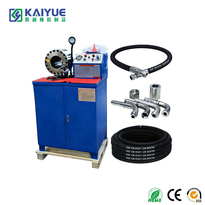
For medium to high-pressure applications, crimped fittings are absolutely mandatory. A specialized crimping machine uses immense hydraulic force to permanently compress the metal collar of the fitting around the rubber, biting deep down into the steel wire reinforcement. This creates a permanent, cold-flow seal that ensures the connection can withstand the full 4 to 1 safety factor without leaking or blowing off under heavy impulse loads.
When procuring fluid conveyance components, purchasing agents often focus intensely on dimensional specifications and material compatibility, inadvertently treating pressure capabilities as a secondary checklist item. In harsh industrial environments, miscalculating or misunderstanding these capabilities can lead to catastrophic system failures, severe safety hazards, and exorbitant downtime costs. By analyzing empirical data from field failures, engineers have identified several recurring procurement errors regarding pressure specifications.
One of the most critical errors in hydraulic system design and component procurement is selecting a product based solely on the system’s average continuous operating pressure. In dynamic fluid power systems, the rapid opening and closing of valves, sudden cylinder stops, or aggressive pump start-ups generate hydrodynamic shockwaves. This is commonly known as the water hammer effect.
These instantaneous pressure spikes can easily exceed the system's normal operating pressure by 200 to 300 percent. If a buyer selects a rating exactly matched for the average system pressure, a sudden surge will push the reinforcement beyond its maximum working limit, accelerating metal fatigue and eventually causing a blowout. When specifying components for high-impulse applications, buyers must calculate the absolute peak surge pressure. In these rigorous environments, opting for an SAE 100 R5 standard Steel Wire Reinforced Hydraulic Hose provides the structural rigidity required to withstand aggressive pressure fluctuations without excessive volumetric expansion.
Application Type | Normal Operating Pressure | Typical Surge Multiplier | Required Hose Rating Minimum |
|---|---|---|---|
General Fluid Transfer | 1,000 PSI | 1.1x to 1.2x | 1,200 PSI |
Agricultural Machinery | 2,500 PSI | 1.5x to 1.8x | 4,500 PSI |
Heavy Construction Equipment | 4,000 PSI | 1.8x to 2.2x | 8,800 PSI |
Industrial Stamping Presses | 5,000 PSI | 2.0x to 2.5x | 12,500 PSI |
Factory pressure ratings are established under highly controlled laboratory conditions. However, the operational reality involves constant exposure to harsh environmental variables. Buyers frequently make the mistake of assuming a product will maintain its factory pressure rating indefinitely, regardless of its operating environment.
External factors such as ultraviolet radiation, ozone exposure, extreme ambient temperatures, and physical abrasion actively degrade rubber compounds over time. When the outer cover cracks due to ozone degradation or wears thin from rubbing against vibrating machinery, the internal reinforcement layer becomes exposed to moisture and corrosive elements. Once steel wire begins to rust or textile braiding frays, structural integrity is lost. Consequently, the actual burst pressure drops significantly below its original specification. Buyers must account for environmental hazards by selecting specialized abrasion-resistant or UV-stabilized covers to ensure the rating remains valid throughout the intended service life.
Environmental Factor | Effect on Structure | Impact on Pressure Rating | Mitigation Strategy |
|---|---|---|---|
UV and Ozone | Hardens and cracks the outer rubber cover. | Exposes reinforcement, leading to rapid pressure capacity loss. | Specify ozone-resistant synthetic rubber covers like Neoprene. |
Physical Abrasion | Wears away the cover through constant friction. | Weakens the physical restraint against internal pressure. | Use protective sleeves or specify ultra-high molecular weight covers. |
Chemical Exposure | Softens or dissolves the elastomer compounds. | Causes localized swelling and immediate loss of pressure resistance. | Verify precise chemical compatibility using industry resistance charts. |
Another frequent oversight is mismatching the reinforcement architecture with the system's unique pressure profile. Buyers sometimes substitute types based on price or immediate availability, blatantly ignoring the engineering principles behind the construction. Attempting to use a textile-braided line in a medium-pressure application simply because its static burst pressure seems sufficient is a dangerous miscalculation, as textiles cannot handle dynamic pressure cycling. Conversely, over-specifying with a heavy multi-spiral line for a simple return application introduces unnecessary costs and severe routing difficulties due to inherent stiffness.
As previously mentioned, pressure ratings are intrinsically linked to temperature. The standard maximum working pressure printed on a layline is typically calculated at an ambient and fluid temperature of 68 degrees Fahrenheit. As temperatures rise, the thermodynamic properties of the rubber change. The elastomers soften, and the adhesive bonds between the inner tube, reinforcement, and outer cover weaken. Operating at maximum pressure while simultaneously pushing the maximum temperature limit is a guaranteed recipe for premature, messy failure.
When your machinery's uptime is on the line, selecting the right fluid conveyance component demands a meticulous evaluation of your entire system. You must carefully balance construction types with specific environmental needs, ensuring that the assembly can safely handle the rigorous demands of your facility. By consistently applying the STAMPED model, you safeguard daily operations and prevent shockingly expensive downtime. Most importantly, never exceed the maximum working pressure limits established by the manufacturer. Accurate pressure ratings are the absolute bedrock of workplace safety and extended system longevity. Ready to upgrade your facility's safety and performance? Visit https://www.kaiyuerubber.com to explore a comprehensive catalog of industry-compliant solutions and find the exact product specifications tailored to your high-pressure requirements.
Absolutely not. Burst pressure is the absolute destruction point of the assembly, determined during destructive laboratory testing. It is not an operational metric. Industry standards enforce a strict safety factor, typically 4 to 1 for hydraulic applications. This means if a product has a burst pressure of 12,000 PSI, its maximum safe working pressure is only 3,000 PSI. Operating anywhere near burst pressure guarantees catastrophic failure, which can result in lethal high-pressure fluid injection injuries, severe environmental contamination, and the total destruction of expensive machinery. Always size your system so that the absolute peak pressure remains at or below the maximum working pressure printed on the layline.
The primary difference lies in the manufacturing geometry of the steel wire and its response to dynamic pressure. In a single wire braided construction, high-tensile steel wires are woven in an overlapping, crisscross pattern. This braided design allows it to remain relatively flexible, making it ideal for medium-pressure applications requiring tight routing. In contrast, a multi-spiral reinforced build features layers of wire wrapped in alternating, parallel directions without crossing over one another. This rigid spiral architecture prevents the wires from shifting, virtually eliminating volumetric expansion. Spiral builds are mandatory for ultra-high-pressure and high-impulse applications, though this immense strength comes at the cost of flexibility.
Pressure spikes occur in milliseconds, meaning standard mechanical dial gauges are far too slow to register them. To accurately detect surges, technicians must install digital pressure transducers connected to an oscilloscope or a high-speed data logger capable of capturing thousands of readings per second. Visually, there are several warning signs. If the line violently twitches, jumps, or elongates significantly every time a valve actuates, it is absorbing hydrodynamic shock. Additionally, premature weeping at the crimped fittings indicates that internal surges are exceeding the holding force of the metal coupling.
The structural pressure rating itself, meaning the maximum PSI the materials can safely contain, does not change regardless of length. A one-foot section and a fifty-foot section of the exact same build will have identical working and burst pressure limits. However, the length dramatically affects the system pressure delivered to the end tool due to fluid friction. As liquid travels through a longer line, friction against the inner tube causes a pressure drop. To compensate for this drop over long distances, engineers often must increase the inner diameter to reduce fluid velocity, which loops back into the Size calculation of the STAMPED model.
There is no universal expiration date, as lifespan is entirely dependent on the operating environment, fluid temperature, pressure cycling, and physical routing. However, standard preventative maintenance protocols in industrial settings generally recommend replacement every 1 to 2 years for heavy-duty, continuous-use machinery. For static applications with minimal pressure fluctuations, they might safely last 3 to 5 years. Replacement should always be condition-based. Swap out the component immediately if routine visual inspections reveal exposed wire reinforcement, deep abrasions, localized blistering, or stiffness from heat degradation.
Fluid velocity does not change the physical burst rating of the rubber itself, but it drastically affects the internal environment. If the inner diameter is too small for the required flow rate, fluid velocity increases. This high-speed flow generates excessive internal friction, which creates heat. As we know from the derating principle, excess heat softens the rubber compound and lowers its effective pressure-holding capability. Therefore, properly sizing the line to maintain a safe fluid velocity is critical to maintaining the integrity of the pressure rating.
Mixing and matching brands between the rubber line and the metal fittings is a highly dangerous practice and is strongly discouraged by field engineers. Manufacturers design their hoses and fittings to work together as a highly specific engineered system with exact dimensional tolerances. Using a fitting from Brand A on a line from Brand B compromises the crimp integrity. This mismatch voids safety certifications and drastically increases the risk of the fitting blowing off under high pressure, even if both individual components share the same pressure rating on paper.


