Kaiyue Rubber (Jingxian): Delivering High-Quality Rubber & Silicone Products for Industrial & Daily Applications Worldwide.
English


Views: 0 Author: Site Editor Publish Time: 2026-09-04 Origin: Site


Improper hose sizing causes massive system inefficiencies. You see it on job sites every day: undetected pressure drops, accelerated wear, and catastrophic fitting blowouts in high-pressure industrial environments. Selecting a replacement or specifying a new assembly requires exact dimensional accuracy. A fraction of an inch in variance compromises flow velocity. It accelerates tube erosion and causes hazardous leaks. You must get the measurements right the first time.
Establishing a standardized measurement framework eliminates procurement guesswork. This framework covers Inside Diameter (I.D.), Outside Diameter (O.D.), Overall Length (OAL), and fitting orientations. Accurate sizing ensures operational safety and strict industry compliance. We will break down how to measure these critical dimensions precisely. We will decode the industry-standard dash size system and explore how specialized applications dictate strict sizing tolerances to keep your operations running safely.
I.D. Dictates Flow, O.D. Dictates Fit: Inside Diameter determines fluid velocity and system pressure, while Outside Diameter is critical for selecting compatible fittings and routing through bulkheads.
Dash Sizes Standardize Measurements: Industrial and hydraulic rubber hoses utilize the "dash size" system, representing the I.D. in 1/16-inch increments.
Length Calculations Require Fitting Context: Overall Length (OAL) must account for fitting types, measuring from the seat of standard fittings, the centerline of elbows, or the face of flanges.
Application Dictates Tolerance: High-risk applications require strict adherence to sizing tolerances to prevent vacuum collapse or pressure bursts, with measurements heavily dependent on actual application scenarios.
A successful hose specification relies on strict baseline requirements. You need an optimal flow rate to maintain system efficiency. You need secure fitting retention to prevent dangerous leaks. You also need an adequate bend radius for proper installation. Meeting these criteria requires exact dimensional data. Guesswork leads to immediate mechanical failures or accelerated wear. Every millimeter matters when dealing with pressurized fluids. You must establish a rigid standard for taking and verifying measurements before ordering replacements. Field technicians must understand how dimensional variances impact the entire fluid transfer system.
Restricted flow changes the physics of your fluid transfer system. An undersized inside diameter forces the same volume of fluid through a smaller space. This increases fluid velocity drastically. High velocity generates excessive heat through friction against the inner tube. This heat bakes the elastomer compounds, causing them to harden and crack prematurely. You will also experience severe system pressure drops. Pumps must work harder to push fluid through the restriction. This leads to pump cavitation, seal damage, and eventual mechanical failure. The internal tube will suffer accelerated wear from the abrasive force of high-speed fluid.
Oversizing introduces a different set of mechanical risks. A larger inside diameter leads to sluggish system performance. Fluid velocity drops below optimal levels, reducing the efficiency of hydraulic actuators or transfer pumps. An oversized outside diameter compromises fitting integrity. The fitting shell cannot achieve adequate compression during the crimping process. The ferrule teeth fail to bite into the wire reinforcement. This lack of compression leads to slow leaks or sudden blowouts under pressure. Oversized assemblies also add unnecessary bulk. This extra weight and size complicate installation in tight machinery spaces and increase the risk of external abrasion against moving parts.
Industrial assemblies must meet strict dimensional tolerances. Organizations like NAHAD and ISO mandate these specific sizing requirements. Failing to meet these standards voids warranties and creates massive liability. Safety protocols dictate that every assembly must withstand specific burst pressures, typically a 4:1 ratio over the maximum working pressure. These pressure ratings rely entirely on correct sizing and fitting compatibility. You cannot achieve compliance if your initial measurements are flawed. Field technicians must follow standardized measurement procedures to ensure every replacement part meets these rigorous safety codes.
The inside diameter represents the void space where media flows. It is the most critical dimension for system performance. I.D. is the primary metric used to size a line for specific flow requirements. Engineers calculate the necessary gallons per minute (GPM) and select the I.D. to match using a fluid velocity nomograph. A precise I.D. prevents turbulent flow and minimizes pressure loss over long distances. You must measure the I.D. accurately to ensure the new assembly matches the original equipment specifications perfectly. Even a slight reduction in I.D. can bottleneck an entire industrial process.
The outside diameter measures the total cross-section of the assembly. This includes the inner tube, the reinforcement layers, and the outer protective cover. O.D. plays a massive role in fitting selection. Crimping and swaging machines require exact O.D. measurements to apply the correct compression force. If the O.D. is too large, the fitting will not slide over the cover. If the O.D. is too small, the crimp will fail to secure the fitting. O.D. also dictates spatial routing constraints. You must ensure the line fits through bulkheads, clamps, and protective sleeves without binding.
You must differentiate between cut length and overall length. Cut length refers strictly to the raw material before any fittings are attached. Overall Length (OAL) represents the total length of the completed assembly. OAL includes the fittings and is measured from specific reference points on those fittings. Ordering based on cut length when you need a specific OAL will result in an assembly that is too short. This forces the material to stretch during installation, placing severe stress on the crimped connections and reducing the service life of the part. Assemblers use a "cutoff factor" to determine exactly how much raw material to cut to achieve the target OAL.
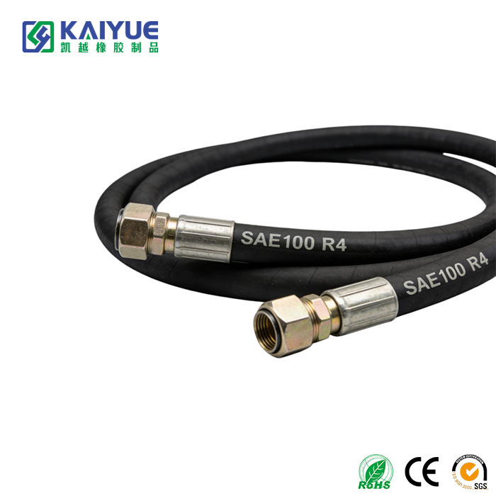
Industrial and hydraulic systems utilize a standardized dash size nomenclature. This system represents the inside diameter in 1/16-inch increments. A -4 size indicates 4/16 of an inch, which simplifies to 1/4 inch. A -8 size indicates 8/16 of an inch, or 1/2 inch. This system applies to the vast majority of common hydraulic and industrial lines. It provides a universal language for technicians, engineers, and suppliers. Understanding this rule eliminates confusion when converting fractional inches to decimal inches for precise caliper measurements.
A reference matrix helps technicians convert dash sizes quickly in the field. Memorizing the most common sizes speeds up the specification process. Use the table below to cross-reference dash sizes with their fractional and decimal equivalents.
Dash Size | Fractional I.D. (Inches) | Decimal I.D. (Inches) |
|---|---|---|
-4 | 1/4" | 0.250 |
-6 | 3/8" | 0.375 |
-8 | 1/2" | 0.500 |
-10 | 5/8" | 0.625 |
-12 | 3/4" | 0.750 |
-16 | 1" | 1.000 |
-20 | 1-1/4" | 1.250 |
-24 | 1-1/2" | 1.500 |
-32 | 2" | 2.000 |
General utility applications often rely on standard fractional sizes. For example, the 5/8-inch diameter is the industry gold standard for general water and utility applications. It provides an optimal balance of flow rate and handling weight. However, high-pressure systems require highly specific dash sizes. You cannot substitute a standard utility size for a high-pressure hydraulic line. The tolerances are too loose. Specialized applications demand exact dash size matching to ensure the reinforcement layers can handle the specified working pressure without failing.
The dash size system is not absolute across all product categories. Certain transportation or specialized industrial lines use dash sizes to refer to the O.D. rather than the I.D. Air conditioning lines, SAE 100R5, and some PTFE lines often follow this exception. You must verify manufacturer specifications before assuming a dash size refers to the inside diameter. Ordering a -8 line based on O.D. when you need a 1/2-inch I.D. will result in a severely undersized assembly. Always consult the technical data sheet for the specific product series you are replacing.
You must prepare the assembly properly before taking any measurements. Ensure the system is completely depressurized. Apply lockout/tagout procedures. Clean and dry the exterior and interior as much as possible. Removing debris and residual fluids is a mandatory first step. Fluids cause caliper jaws to slip, leading to inaccurate readings. Residual chemicals also pose severe safety risks to the technician. You need the right precision tools for the job. Keep Vernier calipers, a Pi tape for O.D. measurements, and a set of pin gauges or drill bits in your inspection kit. Proper tooling guarantees repeatable accuracy.
Measuring the I.D. requires a steady hand and the right technique. You must measure straight across the inside of the opening. Place the caliper jaws from one inner wall to the opposite inner wall. Ensure the calipers cross the exact center of the opening to find the true diameter. Soft elastomers present a unique implementation reality. The pressure of caliper jaws easily deforms soft materials, resulting in an undersized reading. Use a drill bit or pin gauge set for these soft materials. Insert the gauge into the opening until you find a snug fit without stretching the material. The size of that gauge is your exact I.D.
The O.D. dictates your fitting compatibility and crimp specifications. Use a Pi tape or Vernier calipers to measure the outer cross-section. A Pi tape wraps around the circumference and calculates the exact average diameter automatically. This is the most accurate method for field technicians. If you use calipers, you must measure in multiple spots around the circumference. Used lines often suffer from ovality or uneven wear. Taking multiple readings allows you to calculate an accurate average O.D. Never rely on a single caliper measurement on a part that has been in service. The cover may have swelled or flattened over time.
Measuring OAL requires an understanding of fitting reference points. You do not simply measure from end to end. The reference point changes based on the fitting style. Follow this standard procedure for accurate length calculation:
Identify the fitting type on both ends of the assembly.
For standard male or female straight fittings, measure from the internal sealing seat. This is where the fitting mates with the opposing adapter.
For 45-degree and 90-degree elbows, measure to the centerline of the fitting block. Do not measure to the outer curve or the very end of the threads. The centerline dictates the actual routing path.
For fixed and floating flanges, measure to the outermost face of the flange. This is the flat surface that mates against the opposing flange face.
For JIC and SAE threaded connections, measure to the end of the sealing cone, not the end of the swivel nut.
Pull the assembly taut, but do not stretch it, before taking the final tape measure reading.
Specifying a chemical delivery hose requires strict attention to fluid dynamics. Flow rate requirements dictate the I.D. entirely. You must size the I.D. to prevent turbulent flow. Turbulent flow creates aggressive friction that degrades the inner tube during chemical transfer. This degradation contaminates your product and destroys the assembly. You must also balance the I.D. with the required bend radius. A larger I.D. increases the minimum bend radius. If your delivery environment features tight corners, you must calculate whether the required I.D. can physically make the bend without kinking.
Suction applications demand robust structural integrity. When sizing a chemical suction hose, wall thickness and O.D. are critical factors. The wall must be thick enough to house a helical wire reinforcement. This wire prevents vacuum collapse when the pump draws fluid. Proper sizing maintains the integrity of this helical wire. If the O.D. is undersized, the wall thickness is compromised. A compromised wall will flatten under negative pressure, restricting flow and potentially snapping the internal wire. You must verify the vacuum rating alongside the dimensional measurements.
Discharge applications operate under positive pressure and frequent temperature fluctuations. Tolerances for a chemical discharge hose focus heavily on precise O.D. measurement. High-pressure discharge conditions require flawless fitting retention. Temperature fluctuations during chemical transfer cause the elastomer to expand and contract dimensionally. This expansion requires specific crimp diameter tolerances. If the initial O.D. measurement is wrong, the crimp will loosen as the material heats up. You must account for thermal expansion when selecting the ferrule and calculating the final crimp diameter.
Taking dimensions from an old, failed assembly introduces massive implementation risks. Materials stretch, swell, and collapse over time. Chemical exposure causes elastomers to swell, artificially increasing the O.D. and decreasing the I.D. High pressure causes the overall length to shrink or elongate. To mitigate this risk, measure near the fitting where deformation is minimal. The material clamped under the ferrule retains its original dimensions better than the exposed body. If the assembly is severely degraded, refer directly to the original equipment specifications rather than trusting field measurements.
Focusing solely on flow rate often leads to routing failures. Selecting an assembly with the correct I.D. but an overly thick O.D. violates the minimum bend radius. Thicker walls resist bending. Forcing a thick assembly into a tight routing path leads to immediate kinking. Kinking destroys the reinforcement layers and creates a severe flow restriction. You must verify the minimum bend radius specification against your actual machinery layout. If the space is too tight, you may need to select a different reinforcement style, such as a braided construction instead of a spiral construction.
Dimensional choices directly impact pressure capabilities. There is a strict trade-off between larger I.D. assemblies and their maximum working pressures. Larger I.D. assemblies provide better flow but inherently possess lower pressure ratings compared to smaller I.D. assemblies of the exact same construction. You cannot simply increase the I.D. to improve flow without verifying the new pressure rating. You must account for dynamic pressure spikes. A system operating at 2,000 PSI may experience momentary spikes up to 3,000 PSI when valves close rapidly, known as the water hammer effect. Your selected dimensions must support a working pressure that handles these dynamic spikes safely.
Accurate rubber hose measurement is a strict technical requirement that dictates system performance, safety, and component longevity. Base your procurement decisions on exact I.D. for optimal flow and precise O.D. for fitting compatibility. Calculate your OAL from the correct fitting reference points based on your actual application scenarios. Guessing dimensions leads to downtime, leaks, and safety hazards.
Consult a certified assembler to verify your dimensional tolerances before ordering.
Review manufacturer specification sheets to confirm dash size meanings for specialized products.
Inspect existing assemblies for wear, swelling, or deformation prior to taking any measurements.
Standardize measurement tools, like Pi tapes and pin gauges, across your entire maintenance team.
A: Inside Diameter (I.D.) measures the empty space inside the tube and dictates fluid flow rate and velocity. Outside Diameter (O.D.) measures the total width, including the cover and reinforcement, and is critical for selecting compatible fittings and routing through tight spaces.
A: Do not use caliper jaws, as they will compress the soft elastomer and provide an undersized reading. Instead, use pin gauges or the smooth shank of a drill bit. Insert the gauge into the opening to find a snug fit without stretching the material.
A: The dash system measures the inside diameter in 1/16-inch increments. A -8 size equals 8/16 of an inch. This fraction simplifies to a 1/2-inch inside diameter, which is a standard measurement in hydraulic and industrial applications.
A: You must measure to the centerline of the angled fitting. Do not measure to the very end of the threads or the outer curve of the bend. Measuring from centerline to centerline ensures the assembly fits the actual routing path.
A: Yes. The difference between the I.D. and O.D. dictates the wall thickness and the amount of reinforcement. A properly sized wall thickness determines the maximum pressure rating and provides the necessary resistance against vacuum collapse in suction lines.
A: Measure the assembly at the very end, directly over the fitting barb. The material clamped under the ferrule is least likely to have swelled from media exposure. If the entire length is deformed, consult the original equipment manual for exact specifications.
A: Residual fluids or debris cause calipers and Pi tapes to slip, leading to inaccurate O.D. or I.D. readings. Furthermore, residual chemical media poses severe exposure risks to the technician handling the assembly during the inspection process.


